

The dry gas seal is a crucial “gas barrier” in a compressor. It’s not installed inside the impeller or outside the piping, but rather at the point where the compressor shaft passes through the housing—the shaft end seal. This is typically located within a sealing cavity, sealing seat, or sealing box. Its core function is to create a stable seal between the high-speed rotating shaft and the stationary housing, preventing process gas leakage and reducing the risk of lubricating oil entering the process side. For centrifugal compressors, natural gas compressors, and process gas compressors, the dry gas seal is often installed at the shaft seal position on both the drive end (DE) and the non-drive end (NDE). In dual-end structures or special units, dry gas seal systems may be installed at both ends.
So, where exactly is the dry gas seal installed?
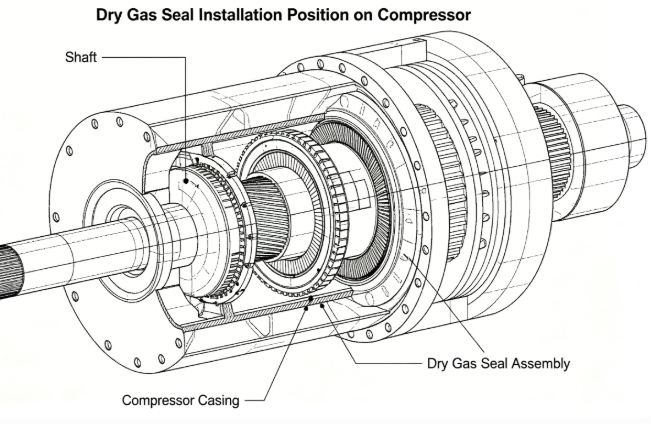
The dry gas seal is typically installed at the sealing point where the compressor shaft exits the housing. This location must withstand the high-speed rotation of the shaft while preventing leakage of the high-pressure medium inside the compressor. Therefore, a more precise solution than traditional contact seals is required. A dry gas seal typically consists of a rotating ring, a stationary ring, a sealing gas control system, a sealing chamber, a throttling element, and auxiliary piping. The part that actually performs the sealing function is located near the shaft seal end face.
Furthermore, dry gas seals are generally not directly exposed to the external environment but are installed within the end cover sealing chamber of the compressor housing. A dedicated working space is formed inside the sealing chamber. Dry gas enters the sealing surface through the control system, forming an extremely thin gas film between the rotating and stationary end faces, thus achieving a non-contact seal. In other words, although its location is close to the shaft end, it is not “randomly attached to the outside of the shaft,” but rather has a clearly defined installation chamber and supporting system.
From an equipment layout perspective, the dry gas seal is usually located at the compressor’s shaft end outlet, after the bearing, near the coupling, and inside the end seal box of the housing. It is installed here because this is precisely the only channel connecting the rotating shaft to the outside world; if this location loses its seal, the stability of the entire compressor will be affected.
How are dry gas seals installed and how do they work?
The installation of a dry gas seal is not simply a matter of putting it on and calling it a day; it’s a complete process from positioning and assembly to commissioning.
- Confirm Installation Location and Structure
Before installation, the compressor’s structural type must be confirmed. The installation location of the dry gas seal may vary slightly between different models, but the principle is always around the shaft penetration point. Installers need to confirm whether it’s a single-end seal, double-end seal, or a series/sequential structure before deciding on the layout of the sealing chamber, piping, and control system.
- Clean the Sealing Chamber and Shaft Surface
Any dust, oil, or metal shavings inside the sealing chamber can disrupt the gas film stability; therefore, thorough cleaning is essential before installation. The shaft sleeve, sealing end face, locating shoulder, and related grooves must also be inspected to prevent scratches, uneven wear, or geometric errors that could affect installation accuracy.
- Install the Sealing Components
Dry gas seals are usually installed as components within the sealing housing. During installation, ensure correct orientation, accurate positioning, and appropriate compression. Because it has high requirements for coaxiality and end face flatness, assembly must be performed according to the manufacturer’s specifications; it cannot be forced in based on experience.
- Connecting the Sealing Gas and Buffer System
After installation, auxiliary systems such as filtration, pressure regulation, throttling, and venting must be connected. The sealing gas is not arbitrarily blown in; it is strictly treated clean dry gas, and its pressure, temperature, and flow rate must meet design values.
- Commissioning and Trial Operation
Before formal commissioning, the sealing gas pressure difference, leakage path, alarm interlocks, and shaft vibration must be checked. Only after confirming gas film stability and normal sealing surface condition can continuous operation begin.
Why Must It Be Installed This Way?
The dry gas seal is installed in the shaft end sealing cavity because this location possesses the dual attributes of “must seal” and “most suitable for sealing.” What truly determines success or failure is not just where it is installed, but how it is installed, matched, and controlled.
- The Installation Position Must Serve the Shaft Centerline
Dry gas seals rely on the end-face gas film for operation, therefore they are most susceptible to eccentricity and vibration. The installation position must be strictly aligned with the compressor main shaft centerline; otherwise, the gap between the dynamic and static rings will be uneven, leading to leakage at best and damage to the end-face contact at worst. This is why the sealing cavity is usually custom-machined, not temporarily added.
- The sealing cavity space determines sealing stability
A dry gas seal is not just a single component, but a “sealing system.” The volume of the sealing cavity, the discharge path, the pressure relief channel, and the cooling conditions all affect its operating condition. If the cavity structure is unreasonable, gas may form eddies, accumulate liquid, or cause localized overheating, leading to seal failure.
- The accuracy of the bushing and end face before installation is critical
Dry gas seals have very high requirements for bushing surface roughness, circular runout, and end face perpendicularity. Because it relies on an extremely thin gas film for operation, even slight surface defects can disrupt the continuity of the gas film. Many field problems are not caused by a faulty seal body, but by bushing scratches, coaxiality deviations, or assembly errors.
- Sealing gas parameters must be strictly controlled
Dry gas seals require a continuous supply of clean, dry, and stable-pressure sealing gas. If the pressure is too low, the gas film cannot be established; if the pressure is too high, it may increase leakage and system load. Flow rate, filtration accuracy, dew point, and oil content must all meet requirements; otherwise, even the best seal will not perform effectively.
- Installation Location Often Accompanied by Auxiliary Systems
Dry gas seals typically do not operate “alone.” They are usually accompanied by filters, pressure regulating valves, control panels, exhaust lines, venting systems, etc. Although these systems may not appear to be on the seal itself, they directly determine the seal’s lifespan. In other words, although the dry gas seal is installed on the shaft end, it is actually operating as a “complete system.”
Why Do Materials Affect the Effect of Installation Location?
The stable operation of a dry gas seal depends not only on the installation location and process but also closely on the choice of materials. The frictional characteristics, temperature resistance, corrosion resistance, and dimensional stability of different materials directly affect the sealing effect.
- Dynamic and Static Ring Materials
Common materials include silicon carbide, tungsten carbide, and graphite composites. Silicon carbide has high hardness and good wear resistance, suitable for high-speed, high-pressure conditions; tungsten carbide has high strength and good impact resistance, suitable for scenarios with large fluctuations in operating conditions; graphite materials have good lubrication and adaptability under specific pairings. 1. **Incorrect Material Selection:** Incorrect material selection can easily lead to end-face wear or thermal cracking.
- Material for Auxiliary Sealing Components
Auxiliary materials such as O-rings, lip rings, and retaining rings often use fluororubber, perfluororubber, or PTFE. Their selection must consider the medium composition, temperature range, and aging rate. For example, ordinary rubber is prone to failure under high temperatures or highly corrosive media, causing the sealing cavity to lose its isolation function.
- Material for Metal Structural Components
Structural components such as springs, glands, bushings, and locating rings often use stainless steel or corrosion-resistant alloys. Because these components need to withstand pressure, vibration, and media erosion over long periods, insufficient material rigidity or poor corrosion resistance can cause dimensional drift, ultimately affecting the accuracy of the seal installation position.
- Material for Sealing Gas Treatment
Sealing gas filter elements, pipelines, and valves cannot be ignored. Even with the best seal material, if the incoming gas contains oil, water, or particles, it will accelerate end-face wear. Often, material selection is not just about the seal itself, but about the material combination of the entire sealing system.
Why must dry gas seals be installed on the shaft end, and not elsewhere?
This is because the truly crucial seal for a compressor is located where the rotating shaft exits the stationary housing. The impeller operates inside the housing, and the piping transports the gas, but only the shaft end creates a “dynamic leakage channel.” Without a seal here, process gas would leak along the gap between the shaft and the housing, and lubricating oil could potentially enter the process side. The dry gas seal is installed at the shaft end not for convenience, but because this is the most critical, sensitive, and fault-tolerant location in the entire compressor.
The compressor’s dry gas seal isn’t installed in “any ordinary location,” but specifically at the shaft end where the main shaft passes through the compressor housing. This seemingly small location is critical to the safe, stable, and long-term operation of the entire system. It must block the high-pressure gas inside without affecting the high-speed rotation of the shaft, and it must work in conjunction with a clean and stable sealing gas system. Because of these high requirements, the installation location, precision, material selection, and auxiliary systems of the dry gas seal cannot be taken lightly. Many people, upon first looking at a compressor, might think the seal is just a small component, but the reality is quite the opposite. Although small in size, the dry gas seal acts as the “gatekeeper” of the entire system. It stands between the shaft and the housing, responsible for retaining the gas that should remain in the machine and keeping out impurities that shouldn’t get in. As long as the installation position is correct, the assembly is standardized, the materials are suitable, and the gas source is stable, it can work quietly for a long time; however, if the position is incorrect, the precision is insufficient, or the system is incompatible, it may cause a series of problems such as leakage, vibration, and shutdown.


