

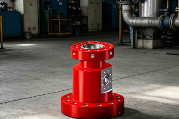
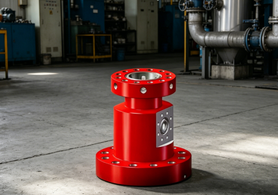
The “casing slip-through system” in casing and pipe slip-through steering drilling is mainly used for the controlled slip-throughing, guiding, and positioning of the casing during drilling or cementing operations, ensuring the casing is smoothly run into the wellbore and remains aligned. It is typically used in conjunction with clamping devices, steering structures, and wellhead equipment, and is a crucial auxiliary system ensuring casing running safety and wellbore quality.
What is a Casing Slip-Through Steering System?
A casing slip-through steering system refers to a mechanical auxiliary system used in drilling operations to controllably move and position the casing or tubing string through specialized clamps, steering structures, and slip-through devices. Its core functions are:
• Controlling the path of the casing into the wellbore
• Reducing friction and jamming between the casing and the wellbore
• Improving the concentricity of the casing during installation
• Reducing the risk of wellhead and downhole accidents.
During directional drilling, due to potential wellbore deviations, large dogleg angles, or irregular well diameters, the casing is prone to wear, jamming, or even instability without a sliding guide system. Therefore, this system is essentially a “guided control tool that allows the casing to smoothly enter the wellbore.” It typically includes a casing clamping device, a sliding guide rail, a limiting mechanism, and auxiliary detection components.
How to use a casing sliding system correctly?
The correct use of a casing sliding system involves a complete process including preparation, installation, sliding operation, inspection, and maintenance.
- Design and Pre-Operation Preparation
Before construction, a design matching process needs to be performed based on the well depth, wellbore trajectory, casing specifications, and formation conditions to determine the load-bearing capacity and guide angle of the sliding device. Different well sections have different requirements for sliding accuracy; highly deviated wells or horizontal wells require higher precision guide control.Simultaneously, it is necessary to check whether the ferrule device matches the outer diameter of the casing, ensuring reasonable clamping force and avoiding slippage or excessive tightness.
- Correct Installation of the Ferrule and Sliding Guide Device
During installation, it is essential to ensure that the guide rail is aligned with the wellhead centerline. The ferrule must clamp evenly against the outer wall of the casing to avoid localized stress concentration. The sliding guide mechanism should be well lubricated to prevent jamming. After installation, a no-load test is required to confirm smooth sliding.
- Casing Sliding Operation Process
During casing lowering, the descent speed and direction are gradually controlled using the sliding device to prevent free fall or sudden jamming. Operators should maintain a stable advance rhythm and adjust the sliding speed based on downhole resistance feedback. If abnormal resistance occurs, sliding should be stopped immediately and the cause investigated.
- Post-Operation Inspection
After the casing is in place, the ferrule, guide device, and sliding rail need to be inspected to confirm there is no deformation, wear, or abnormal displacement. Usage should be recorded to provide reference data for the next operation.
Why are casing sliding systems prone to problems?
Although the casing sliding system has a simple structure, it is prone to problems under high-load operations. The core technical challenges lie in “force control + guidance accuracy + friction management.”
Improper control of ferrule clamping force:
The ferrule is a critical component that directly acts on the outer wall of the casing. If the clamping force is too small, the casing will slip during sliding; if the clamping force is too large, it may cause damage or deformation to the outer wall of the casing. The correct clamping force must be matched with the casing material, wall thickness, and surface treatment.
Deviation in guide track concentricity:
The guide device must be strictly coaxial with the wellhead center. If there is eccentricity, the casing will generate lateral forces during sliding, leading to increased wear and even jamming. This deviation will be gradually amplified in long well sections.
Uneven frictional resistance leading to jamming:
The friction between the casing and the well wall is dynamically changing, especially in well sections with a large dogleg. If lubrication is insufficient or the well wall is irregular, local high-resistance areas will appear, resulting in discontinuous sliding.
Structural Fatigue and Long-Term Deformation:
The sliding guide device is subjected to repeated loads over a long period. If the material strength is insufficient or the structural design is unreasonable, deformation or fatigue cracks are likely to occur. This directly affects the guiding accuracy and safety.
Unstable Operating Rhythm:
Human operation is also a critical issue. If the sliding speed fluctuates, it will lead to increased impact loads, causing uneven stress on the ferrule and guide structure, thus accelerating wear.
Why do materials determine system reliability?
The reliability of the casing sliding guide system largely depends on the appropriateness of material selection, especially for load-bearing and friction components.
- Ferrule Material Selection
The ferrule must possess high strength and good compressive strength, typically using high-strength alloy steel or heat-treated tool steel. For high-load well sections, surface hardening treatment may also be used to improve wear resistance and fatigue resistance.
- Guide Rail Material
The guide rail needs to withstand continuous sliding friction, therefore wear-resistant steel or surface coating materials (such as hardened layers or sprayed carbide coatings) are often used. The core of material selection is to reduce the coefficient of friction and increase service life.
- Materials for Sliding Contact Components
Sliding surfaces typically require a combination of low-friction, high-wear-resistant materials, such as metal-polymer composites or self-lubricating coatings, to reduce the risk of jamming.
- Materials for Fasteners and Connectors
Bolts, pins, and other connectors must possess high shear resistance and fatigue resistance. They are typically made of high-strength alloy steel and undergo anti-corrosion treatment to withstand the complex well site environment.
Common Problems
What are the most common causes of failure in casing sliding systems?
In actual operation, most failures in casing sliding systems are not due to sudden equipment damage, but rather a combination of uneven stress, improper operation, and guide deviation. The most common issues are inappropriate clamping force and misalignment of the guide rails. Insufficient clamping force will cause slippage, while excessive force will damage the casing; misalignment will lead to lateral friction during casing insertion, increasing the risk of jamming. In addition, insufficient lubrication and unstable sliding rhythm are also common contributing factors.
The function of the casing sliding guide system is to ensure that the casing moves more steadily, straighter, and more safely when entering the wellbore. Although it may seem like just a few clamps and guide devices, it plays a crucial auxiliary role throughout the drilling process. Without it, the casing can easily deviate, become stuck, or even damage the wellbore in complex wells. Many problems are not due to poor equipment design, but rather to a lack of control over details during use, such as uneven clamping of the clamps, misalignment of the guide, inconsistent sliding speed, or inadequate lubrication. These seemingly minor issues can be magnified under high-load operations.


