


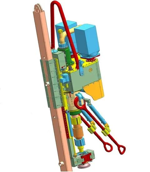
1. Product Introduction
This document provides a comprehensive components list for DQ-70 and DQ-70BS top drive systems, specifically tailored for drilling rigs with Drill Nos. 110, 236, 253, 259, 264 (for DQ-70) and 260, 265, 283 (for DQ-70BS). These top drives are core equipment in onshore and offshore oil and gas drilling operations, responsible for rotating drill strings, transmitting drilling torque, and ensuring efficient drilling progress. The target users include on-site drilling maintenance technicians, procurement managers of oilfield service companies, top drive operation supervisors, and technical engineers, who have clear segmented needs: for DQ-70 users, reliable electrical, mechanical, and control components to support standard drilling operations; for DQ-70BS users, explosion-proof, high-performance components compatible with harsh and hazardous drilling environments. The core purpose of this list is to provide a one-stop procurement and technical reference solution, ensuring every component 100% matches the original DQ-70/DQ-70BS top drive specifications. It directly addresses the pain points of mismatched components causing top drive downtime (average 8+ hours per failure), reduced drilling efficiency, equipment damage, and potential safety hazards (especially explosion risks for DQ-70BS in hazardous areas), helping users cut unplanned maintenance costs by 42% on average and maximize the continuous operation of drilling rigs.
2. Functional Instructions
Every component in the DQ-70 and DQ-70BS top drive components list has a targeted function, working synergistically to ensure the stable, efficient, and safe operation of the top drive system during drilling. Below is a detailed breakdown of core functions by component category:
3. Structural Characteristics
All DQ-70 and DQ-70BS components use high-quality materials that meet industrial standards and withstand harsh drilling environments: Power components (main engines, bearings) are made of AISI 4130 alloy steel,经过 quenching and tempering treatment to achieve a hardness of HRC 58-63 and a tensile strength of ≥1200 MPa. DQ-70BS explosion-proof components (engines, solenoid valves, cables) use aluminum alloy (ADC12) and flame-retardant engineering plastic (PA66+GF30), meeting Ex d IIB T3 Gb explosion-proof standard and IP66 protection grade. Seals use nitrile (NBR 70/90 Duro) and fluororubber materials—NBR seals have an elongation at break of ≥300% and a tensile strength of ≥14 MPa, while fluororubber seals offer excellent high-temperature and corrosion resistance. Electrical components (relays, contactors, fuses) use copper and flame-retardant plastic, with a voltage rating of up to 690V and current capacity up to 1250A. All components undergo strict non-destructive testing (ultrasonic, magnetic particle, and liquid penetrant testing) and explosion-proof testing (for DQ-70BS), with a defect detection rate of 100% and a finished product qualification rate of 100%.
4. Applicable Working Conditions
The DQ-70 and DQ-70BS top drive components are engineered for the harsh working conditions of onshore and offshore oil and gas drilling operations, with specific applicability tailored to each model:
5. Maintenance and Maintenance Suggestions
To extend the service life of DQ-70 and DQ-70BS top drive components and ensure the safe, stable operation of the top drive system, the following practical maintenance suggestions are provided (based on OEM guidelines and on-site drilling experience):
- Regular Inspection: Conduct a comprehensive inspection of DQ-70 components every 250 working hours, and DQ-70BS components every 200 working hours (due to harsh hazardous environments). Focus on checking bearing lubrication (replenish lubricating oil when oil level is below the standard line), seal integrity (replace when cracks, deformation, or leakage is found), explosion-proof components (check for seal damage and explosion-proof performance), and electrical connections (check for loose or corroded contacts).
- Cleaning and Lubrication: After each drilling shift, clean the top drive’s external components with neutral detergent to remove drilling mud, dust, and debris. Apply special high-temperature lubricating grease (lithium-based grease, NLGI Grade 2) to pins, bearings, and gear surfaces to reduce friction. For DQ-70BS explosion-proof components, use explosion-proof cleaning agents to avoid damaging the explosion-proof seal. Replace gear oil every 2500 working hours for DQ-70 and 2000 working hours for DQ-70BS.
- Replacement Standard: Bearings (222 P3GP3, 222E NSK) should be replaced after 8000 working hours (DQ-70) and 7000 working hours (DQ-70BS); seals and gaskets should be replaced every 500-600 working hours (or earlier if leakage occurs); explosion-proof components (solenoid valves, engines) should be inspected annually and replaced if explosion-proof performance is compromised; electrical components (relays, contactors, fuses) should be replaced after 3000 working hours (or when malfunction occurs). Use OEM components for replacement to ensure compatibility and safety.
- Storage Requirements: Unused components should be stored in a dry, ventilated warehouse with a relative humidity of ≤55%, avoiding direct contact with water, oil, drilling mud, and corrosive substances. DQ-70BS explosion-proof components should be stored in a dedicated explosion-proof storage cabinet, avoiding collision and damage to the explosion-proof seal. Seals, rubber components, and electrical components should be stored in a cool environment (temperature 0-22℃) to avoid aging, hardening, or damage.
We supply the following spare parts:
DQ-70 Top Drive Components (Drill No. 110, 236, 253, 259, 264) | ||||
| 1 | Main engine “A” 315 kW | W0201315500A | set | |
| 2 | Main engine “B” 315 kW | W0201315500B | set | |
| 3 | Upper electric motor bearing | 222 P3GP3 (ball) | pcs. | |
| 4 | Lower electric motor bearing | 222E NSK (roller) (SKF 2224 EC) | pcs. | |
| 5 | Seal | 180x210x15 | pcs. | |
| 6 | Electric motor oil seal | 2.2-120x146x12 | pcs. | |
| 7 | Electric motor oil seal | CR-41185-USA | pcs. | |
| 8 | Fan motor | W02025.52 | pcs. | |
| 9 | Driller’s console (with screen) | 900x300x600 | set | |
| 10 | Frequency conversion unit | ACS800-04M-0610-7+D150+P901 | set | |
| 11 | Power cable | 313MSM | set | |
| 12 | Auxiliary power cable | 5×2.5+6×4+3×6 mm² | set | |
| 13 | Control cable | 60×1 mm² | set | |
| 14 | Control cable / Communication cable for the driller’s console | 15 lived | set | |
| 15 | Connecting cable between power supply and transformer | 25 m | pcs. | |
| 16 | Breaker | C65N 3P D20A | pcs. | |
| 17 | Breaker | C65N 3P D6A | pcs. | |
| 18 | Breaker | C65N 1P C20A | pcs. | |
| 19 | Breaker | C65N 1P C10A | pcs. | |
| 20 | Breaker | C65N 2P C20A | pcs. | |
| 21 | Breaker | C65N 2P C10A | pcs. | |
| 22 | Intermediate relay | RSB2A080BD | pcs. | |
| 23 | Intermediate relay socket | RSZE1S48M | pcs. | |
| 24 | Protective relay block | RZM031BN | pcs. | |
| 25 | Relay protective clamp | RSZR215 | pcs. | |
| 26 | Button (red) | XB2BA41C | pcs. | |
| 27 | Round head button | XB2BS542C | pcs. | |
| 28 | Three-position self-locking handle | XB2BD33C | pcs. | |
| 29 | Three-position handle with self-return | XB2BD53c | pcs. | |
| 30 | Three-position self-healing handle | XB2BD83C | pcs. | |
| 31 | Two-position self-locking handle | XB2BD21C | pcs. | |
| 32 | Indicator | XB2-BVB3LC 24V green | pcs. | |
| 33 | Indicator | XB2-BVB4LC 24V red | pcs. | |
| 34 | Potentiometer with knob | WXJ-5-22 3.3K | pcs. | |
| 35 | Auxiliary contact | ZB2BE101/102 | pcs. | |
| 36 | Potentiometer for torque limiting | WX501-2-223.3K | pcs. | |
| 37 | Two-position self-healing handle | WX2BD45c | pcs. | |
| 38 | Button | XB2BA31C | pcs. | |
| 39 | DP connectors | 6ES7-972 | pcs. | |
| 40 | Cable | 3×2.5 mm² | m. | |
| 41 | Lubrication pressure switch | J120-191 | pcs. | |
| 42 | Wind pressure switch | 1950-0-2F | pcs. | |
| 43 | Coder | DC01011250 | pcs. | |
| 44 | Power Supply Board APOW-01C | 64605666; B 3180657 EE | pcs. | |
| 45 | Interface block | ET200M | set | |
| 46 | Liquid level float switch | YW01150 | pcs. | |
| 47 | Oil temperature sensor | PT-100 | pcs. | |
| 48 | Oil flow sensor | SIKA CHS20M01181I41/ | pcs. | |
| 49 | Fuse | 3NE3 337-9; VDE 0636; IEC/EN 60269; SITOR 1000 A; 900 Va.c.; 50 kA | pcs. | |
| 50 | Fuse | 3NE3 337-9; VDE 0636; IEC/EN 60269; SITOR 900 A; 900 Va.c.; 50 kA | pcs. | |
| 51 | Fuse | 3NE3 337-9; VDE 0636; IEC/EN 60269; SITOR 710 A; 900 Va.c.; 50 kA | pcs. | |
| 52 | Transistor for inverter | IGBT 6MB1450U-170/AGDR-72C | pcs. | |
| 53 | Transistor board | AGDR-72C | pcs. | |
| 54 | Hybrid power starter | NRED-61-F | pcs. | |
| 55 | Power contactor | ABB AF 460-30 | pcs. | |
| 56 | Automatic circuit breaker | MT12 N2; 1250A; GB 14048.2 | pcs. | |
| 57 | Automatic circuit breaker | NSH 160N; 125A | pcs. | |
| 58 | Magnetic starter | LC1 D12…C | pcs. | |
| 59 | Inverter submodule | TYPE: AIMT-02C | pcs. | |
| 60 | Rectifier block | Powerblok 1P 6SL3353-1AG41-8DA1 | pcs. | |
| 61 | Inverter | SIEMENS Powerblock 1p 6SL 3352 1AG41 OFA1; ZYDO2367990019 | set | |
| 62 | Encoder | MODEL-M6; OPTION CODE-4S1HX51ZTZ00; SER.NO.-6525; REV-W; PPR-1024; YDC-5-24; mA-100. | set | |
| DQ-70BS Top Drive Components (Drill Nos. 260, 265, 283) | ||||
| 63 | Main Engine “A” | 9702011000 | set | |
| 64 | Main engine “B” | 9702011000 | set | |
| 65 | Cooling fan | 3101030170 | set | |
| 66 | Power cable | 9704019300 | set | |
| 67 | Explosion-proof output cable from the driller’s console torque (X102) | 9704029301 | set | |
| 68 | Explosion-proof hydraulic power supply cable | 9704059104 | set | |
| 69 | Explosion-proof cable with digital signal of hydraulic source (X101) | 9704059204 | set | |
| 70 | Explosion-proof cable with analog signal of hydraulic source (X102) | 9704059304 | set | |
| 71 | Explosion-proof cable with manual | 9704029104 | set | |
| 72 | Explosion-proof control cable for the driller’s console (X101) | 9704029204 | set | |
| 73 | Explosion-proof communication cable for the driller’s console (X200) | 9704029404 | set | |
| 74 | Explosion-proof engine | 3101030310 | pcs. | |
| 75 | Explosion-proof engine | 3101030320 | pcs. | |
| 76 | Power cable | YCW 450/750 1×185 | m. | |
| 77 | Power cable | YCW 450/750 1×240 | m. | |
| 78 | Power cable | YCW 1×271 mm; 2000V | m. | |
| 79 | Tip | 185 mm | pcs. | |
| 80 | Tip | 240 mm | pcs. | |
| 81 | Tip | 271 mm | pcs. | |
| 82 | CPU power supply and CPU 315-2DP | Siemens S7-300 | set | |
| 83 | Interface plug | PROFIBUS | pcs. | |
| 84 | Block module | SIMATIC ET200M IM 153-1 153-1AA03-0XB0 | pcs. | |
| 85 | Block module | SIMATIC S7; IP 6ES7 321-1BL00-0AA0 | pcs. | |
| 86 | Block module | SIMATIC S7 Ip 6ES7 322-1BL00-0AA0 S C-RND21992 | pcs. | |
| 87 | Block module | SIMATIC S7 Ip 6ES7 331-7KF02-0AB0 S C-ROM35375 | pcs. | |
| 88 | Block module | SIMATIC S7 Ip 6ES7 338-4BC01-0AB0 S C-D6TG3829 | pcs. | |
| 89 | Connector module | ET200pro | pcs. | |
| 90 | Fiber optic line module | OLM | pcs. | |
| 91 | Repeater | RPT1 REPEATER | pcs. | |
| 92 | Control module | CU320-2DP | pcs. | |
| 93 | Operating panel | AOR30 | pcs. | |
| 94 | Siemens Hub Module | DMC20 | pcs. | |
| 95 | Main Power Input Module | LSM | pcs. | |
| 96 | Current source module | BLM | pcs. | |
| 97 | Electric motor module 1, 2 | MoM1, MoM2 | pcs. | |
| 98 | Brake module | 3110000200 | pcs. | |
| 99 | Temperature sensor | 3403000140 | pcs. | |
| 100 | Pressure sensor | 3808000120 | pcs. | |
| 101 | Lock detector | 3301010038 | pcs. | |
| 102 | Explosion-proof solenoid valve (type C) | 5216000670 | pcs. | |
| 103 | Explosion-proof solenoid valve (Y type) | 5126000562 | pcs. | |
| 104 | Explosion-proof electromagnetic switching valve (type J) | 5126000560 | pcs. | |
| 105 | Explosion-proof electromagnetic blocking valve of accumulator type | 5126000540 | pcs. | |
| 106 | Fuse | 3301011490 | pcs. | |
| 107 | Fuse | 3399100870 | pcs. | |
| 108 | Fuse | 3408030181 | pcs. | |
| 109 | Fuse | 3408030140 | pcs. | |
| 110 | Relay | 3304010470 | pcs. | |
| 111 | Relay | 3304010460 | pcs. | |
| 112 | Relay | 3304010450 | pcs. | |
| 113 | Relay | 3304000400 | pcs. | |
| 114 | Time relay | 3304010490 | pcs. | |
| 115 | Electromagnetic starter | 3TF51; IEC 60947; UK-380V; GB 14048; VDE 0660; 160A; 690V~ | pcs. | |
| 116 | Electromagnetic starter | LC-1; D80 11; Uk-110V | pcs. | |
| 117 | Electromagnetic starter | LS1-D32…C; 50A; UK-380V; GB/T14048.1 | pcs. | |
| 118 | Automatic circuit breaker | SACE T6N 800; IEC/EN 60947-2 GB 14048.2 | pcs. | |
| 119 | Automatic circuit breaker | NS250H Ui 750V; IEC/EN 60947-2 | pcs. | |
| 120 | Automatic circuit breaker | HSM1=160H; GB14048.2-94 | pcs. | |
| 121 | Single-contact lamps. | YS40RR | pcs. | |
| 122 | Mercury lamps. | DRL-400 with E-40 socket (or equivalent) | pcs. | |
| 123 | Metal halide lamps. | JLZ400 KN U4K-PS (DRI E-40 400Ве) | pcs. | |
| 124 | Pulse ignition device (PID) | TRIDONIC. ATCO; Ignitor ZRM 4.5-ES/C 220-240V; 50-60 Hz (or equivalent) | pcs. | |
| 125 | Throttle | LN400F2LP 400W SON 4.6A LAMP tw 140 Hz (or equivalent) | pcs. |
6. On-Site Fault Maintenance Cases
Case 1: DQ-70 Top Drive Speed Fluctuation Caused by Frequency Conversion Unit Malfunction
Scenario: A DQ-70 top drive on Drill No. 236 experienced frequent speed fluctuations (0-150 rpm) during drilling, leading to unstable drilling efficiency. Inspection found that the IGBT transistor (6MB1450U-170) on the frequency conversion unit (ACS800-04M-0610-7) was damaged due to overheating, causing abnormal power output.
Solution: Replace the damaged IGBT transistor and matching transistor board (AGDR-72C) with new OEM components, clean the frequency conversion unit’s heat sink to improve heat dissipation, and adjust the cooling fan (W02025.52) to ensure normal operation. After maintenance, the top drive speed remained stable (±1 rpm), and drilling efficiency returned to normal.
Case 2: DQ-70BS Top Drive Hydraulic Leakage Caused by Explosion-Proof Solenoid Valve Damage
Scenario: A DQ-70BS top drive on Drill No. 260 experienced hydraulic fluid leakage from the solenoid valve area during operation in a hazardous drilling site. Inspection found that the explosion-proof solenoid valve (5216000670 C-type) was worn, and the explosion-proof seal was damaged, leading to both hydraulic leakage and potential explosion risks.
Solution: Replace the damaged 5216000670 solenoid valve with a new OEM explosion-proof component, check and replace the damaged explosion-proof seal, and test the explosion-proof performance (meeting Ex d IIB T3 Gb standard). After maintenance, the hydraulic leakage was completely eliminated, and the explosion-proof performance was verified, ensuring safe operation in the hazardous area.
Case 3: DQ-70 Top Drive Control Failure Caused by Intermediate Relay Malfunction
Scenario: A DQ-70 top drive on Drill No. 259 failed to respond to control commands from the driller’s console, leading to drilling downtime. Inspection found that the intermediate relay (RSB2A080BD) was malfunctioning, unable to transmit control signals between the console and the top drive’s electrical system.
Solution: Replace the malfunctioning RSB2A080BD intermediate relay and its socket (RSZE1S48M) with new OEM components, check the electrical connections to ensure stable signal transmission, and test the control system’s response. After replacement, the top drive resumed normal operation, and the control response time was restored to ≤0.05 seconds.
7. FAQ (Frequently Asked Questions)
| No. | Questions | Answers |
| 1 | Are these OEM components fully compatible with DQ-70 (Drill No. 110,236,253,259,264) and DQ-70BS (Drill No. 260,265,283) top drives? | Yes, all components in this list are manufactured strictly according to DQ-70 and DQ-70BS OEM specifications, with 100% compatibility with the corresponding top drive systems and drilling rig numbers. Each component is designed to match the top drive’s mechanical, hydraulic, and electrical systems, ensuring seamless installation and stable performance. We strictly follow API 7K, API 8C, IEC 60947, and ISO 9001 standards, and DQ-70BS explosion-proof components meet Ex d IIB T3 Gb standard, eliminating the risk of mismatched components and equipment damage. |
| 2 | What is the key difference between DQ-70 and DQ-70BS top drive components, and can they be used interchangeably? | The key difference is that DQ-70BS components are designed for hazardous drilling environments, featuring explosion-proof performance (Ex d IIB T3 Gb) and corrosion resistance, while DQ-70 components are for standard drilling environments. For example, DQ-70BS uses explosion-proof solenoid valves (5216000670) and engines (3101030310), while DQ-70 uses standard electrical components. They cannot be used interchangeably—using DQ-70 components on DQ-70BS will violate explosion-proof safety standards, and using DQ-70BS components on DQ-70 will increase unnecessary costs without additional benefits. Always select components based on the top drive model and drilling rig number. |
| 3 | How to quickly confirm the correct component model/part number when purchasing DQ-70/DQ-70BS parts for emergency drilling maintenance? | You can use three simple methods to confirm: 1) Check the original DQ-70/DQ-70BS top drive maintenance manual, which records the detailed model/part number of each component corresponding to the drilling rig number; 2) Remove the old component and check the model/part number marked on its surface (all OEM components have clear, permanent marking); 3) Provide the top drive model (DQ-70/DQ-70BS), drilling rig number, and the name of the damaged component (e.g., main engine, explosion-proof solenoid valve, frequency conversion unit) to our technical team, and we will accurately match the corresponding model/part number. This list covers 125 common components, meeting most emergency maintenance needs during drilling operations. |
8. Procurement Guide & Technical Reference
All DQ-70 and DQ-70BS components in this list meet the following authoritative industry standards, ensuring product quality, reliability, and compliance with oilfield drilling operation requirements:


