
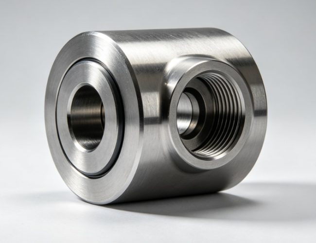
Product Introduction
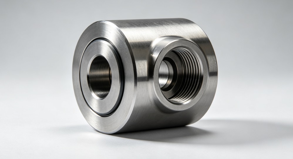
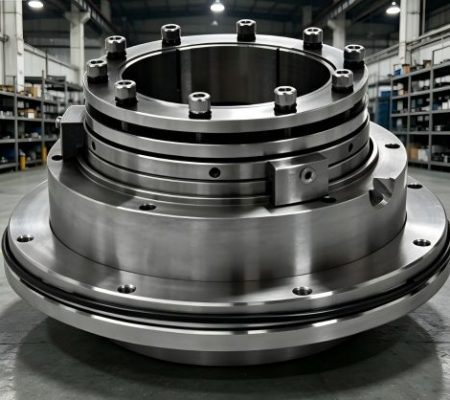
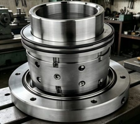
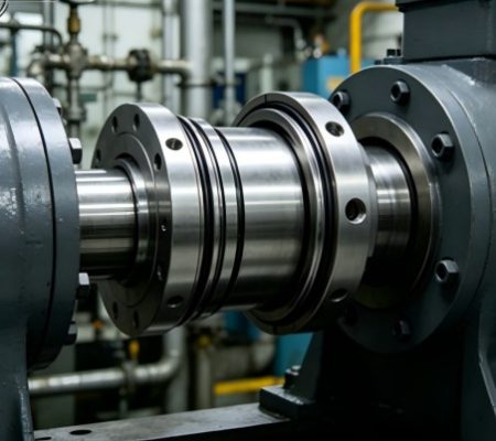
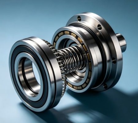
This full CSF-500 fluid end assembly parts collection includes every essential component for complete fluid end rebuilds, valve replacements, liner repairs, sealing overhauls, and manifold maintenance, featuring OEM-compatible dimensions, wear-resistant high-grade materials, and rigorous pressure-testing protocols. From the rugged fluid end studded assembly, bi-metal liner, and valve assembly to suction/discharge manifolds, seals, and high-pressure fasteners, each component is engineered to directly replace original factory parts, eliminating compatibility issues and ensuring seamless integration with the CSF-500 mud pump’s fluid end module. Designed for both scheduled preventive maintenance and emergency high-pressure failure repairs, this kit provides a one-stop sourcing solution for durable, high-performance fluid end components.
Functional Description
- High-Pressure Fluid Displacement: The piston rod, piston nut, and bi-metal liner work in tandem to create pressurized suction and discharge cycles, delivering consistent flow rates of drilling mud at rated operating pressures.
- Flow Control & Sealing: Valve assemblies, valve guides, and valve springs regulate one-way fluid flow, while head seals, O-rings, and gaskets create leak-proof barriers to prevent high-pressure fluid loss.
- Manifold & Flow Distribution: Suction and discharge manifolds route drilling fluid to and from the pump chamber, with baffle plates and filter screens reducing turbulence and blocking abrasive debris.
- Component Retention & Stability: High-strength bolts, studs, nuts, and clamps secure all fluid end components, withstanding extreme pressure pulses and vibration during continuous operation.
- Wear Protection & Longevity: Bi-metal liners and valve guides resist abrasive wear from drilling mud, while cylinder heads and valve pot covers shield internal components from damage and contamination.
Maintenance & Care Recommendations
Follow these industry-standard maintenance protocols to maximize fluid end lifespan and prevent costly high-pressure failures:
- Daily Inspection: Check for high-pressure fluid leaks at seals, flanges, and valve covers; monitor discharge pressure stability and inspect for abnormal noise or vibration.
- Weekly Maintenance: Tighten all high-strength bolts, studs, and nuts to specified torque values; clean filter screen assemblies to remove debris buildup.
- Monthly Service: Inspect valve assemblies and seats for wear or scoring; check bi-metal liners for abrasion damage; replace worn O-rings, gaskets, and head seals.
- Quarterly Overhaul: Disassemble the fluid end to clean pressure chambers and manifolds; inspect piston rods and clamps for wear; calibrate valve spring tension and replace fatigued springs.
- Long-Term Storage: Drain all drilling fluid from the fluid end, coat metal components with anti-corrosive lubricant, and seal all openings to block dust and moisture contamination.
- We supply the following spare parts:
| CSF-500 Fluid End Assembly | ||
| Item No. | Description | Part No. |
| CSF-500 | ||
| 1 | Fluid end studded Assy | CS35001-05.01 |
| 2 | Thread ring | CS35001-05.02 |
| 3 | Cylinder head | CS35001-05.03 |
| 4 | Head seal | CS35001-05.04 |
| 5 | Cylinder head plug | CS35001-05.05 |
| 6 | Cylinder-liner fixer | CS35001-05.06 |
| 7 | O-ring | CS35001-05.07 |
| 8 | Valve cover seal | CS35001-05.08 |
| 9 | Valve pot cover | CS35001-05.09 |
| 10 | Spring guiding | CS33001-05.10 |
| 11 | Valve guide (upper) | CS35001-05.11 |
| 12 | Valve guide retainer | CS35001-05.12 |
| 13 | Bolt | CS35001-05.13 |
| 14 | Stainless steel wire | GB4240-84 |
| 15 | Valve spring | CS35001-05.14 |
| 16 | Valve Assy | CS36001-05.15 |
| 17 | Piston nut | CS35001-05.16 |
| 18 | O-ring | Ø41.2×3.55 |
| 19 | Piston rod | CS35001-05.17 |
| 20 | Bi-metal liner | CS35001-05.18 |
| 21 | Piston rod clamp | CS35001-05.19 |
| 22 | Liner end cover | CS35001-05.20 |
| 23 | Anchor clamp | CS35001-05.21 |
| 24 | Valve guide lower) | CS35001-05.22 |
| 25 | O-ring | Ø150×7 |
| 26 | Bolt GB5780 | 3/8″-10UNC×2″ |
| 27 | Suction manifold | CS35001-05.23.0 0 |
| 28 | Bolt | 1″-8UNC×31/2″ |
| 29 | Nut | 1″-8UNC |
| 30 | Gasket | GB3452.1-82 |
| 31 | Blank flange | CS35001-05.24 |
| 32 | Suction flange | CS35001-05.26 |
| 33 | Suction baffle plate(package) | CS35001-05.27 |
| 34 | Bolt | 1″-8UNC×41/4″ |
| 35 | Nut | 11/4″-8UNC-2B |
| 36 | Suction desurger | CS35001-05.28.0 0 |
| 37 | Elbow Bend | CS35001-05.29.0 0 |
| 38 | Discharge manifold | CS35001-05.30 |
| 39 | discharge baffle plate(package) | CS35001-05.31 |
| 40 | Stud | 11/4″-8UNC×83/8 “ |
| 41 | Nut | 11/4″-8UNC-2B |
| 42 | Filter screen assembly | CS35001-05.32.00 |
| 43 | Elbow Bend | CS35001-05.33 |
| 44 | Male connector | CS35001-05.34 |
| 45 | Connector | CS35001-05.35 |
| 46 | Elbow | CS35001-05.36 |
| 47 | Rubber hose |
Field Fault Repair Cases
Case 1: High-Pressure Discharge Leakage & Pressure Drop
Fault Symptom: Visible fluid leakage at the cylinder head, gradual discharge pressure drop, and reduced mud flow rate.
Root Cause: Worn head seal (CS35001-05.04) and damaged O-ring (Ø150×7) failing to maintain high-pressure sealing integrity.
Repair Solution: Replace the worn head seal and O-ring, re-torque cylinder head bolts to OEM specs, and pressure-test the assembly. Leakage was fully eliminated, and rated discharge pressure was restored.
Case 2: Premature Valve Failure & Flow Instability
Fault Symptom: Erratic suction and discharge flow, unusual clicking noises from the valve chamber, and inconsistent pressure output.
Root Cause: Worn valve assembly (CS36001-05.15) and fatigued valve spring (CS35001-05.14) causing improper valve seating and flow reversal.
Repair Solution: Replace the valve assembly, valve spring, and upper/lower valve guides; clean the valve pot chamber. Flow stability was restored, and pressure output remained consistent during 500+ operating hours.
Case 3: Bi-Metal Liner Wear & Piston Leakage
Fault Symptom: Internal fluid bypass within the pump chamber, reduced pumping efficiency, and visible abrasion on liner surfaces.
Root Cause: Excessive abrasive wear on the bi-metal liner (CS35001-05.18) and damaged piston rod seal, leading to fluid loss during compression cycles.
Repair Solution: Replace the bi-metal liner, piston rod, and matching O-rings; realign the piston rod clamp. Pump efficiency returned to 100% of OEM ratings, with no further bypass issues.
Frequently Asked Questions (FAQ)
| Question | Answer |
| Are these fluid end parts fully compatible with original CSF-500 mud pumps? | Yes, all components are manufactured to OEM dimensional, material, and pressure-rated standards, ensuring direct fitment with Sichuan Petroleum CSF-500 mud pumps without modifications. |
| What is the typical service life of critical fluid end components? | Bi-metal liners last 12–18 months in abrasive conditions; valve assemblies last 6–10 months; seals and O-rings require replacement every 3–4 months, depending on drilling intensity. |
| Can I purchase individual fluid end parts instead of the full assembly kit? | Absolutely, every component (valves, liners, seals, manifolds, fasteners, etc.) is available for separate purchase with matching part numbers for targeted repairs and partial replacements. |
Procurement Guidance
Investing in these CSF-500 mud pump fluid end assembly parts ensures reliable high-pressure fluid handling, minimizes costly unplanned downtime, and reduces long-term mud pump maintenance expenditures. Each component undergoes strict pressure testing to meet API drilling standards, delivering consistent performance in the harshest abrasive drilling environments and serving as a cost-effective, high-quality alternative to OEM parts.
Whether you need a full fluid end rebuild kit, replacement valves and liners, high-pressure seals, or manifold components for emergency repairs, this product line provides complete coverage for all CSF-500 fluid end maintenance needs. These parts not only meet rigorous procurement quality criteria but also act as a trusted technical reference for diagnosing and resolving fluid end-related pressure and flow failures.